
")
Metal Injection Moulding (MIM) – Introduction
Metal Injection Moulding (MIM) is a highly advanced manufacturing process that combines the design flexibility of plastic injection moulding with the material properties of metals.
It enables the cost-effective production of complex geometries in medium to large batch sizes – from around 5,000 to several million parts per year.
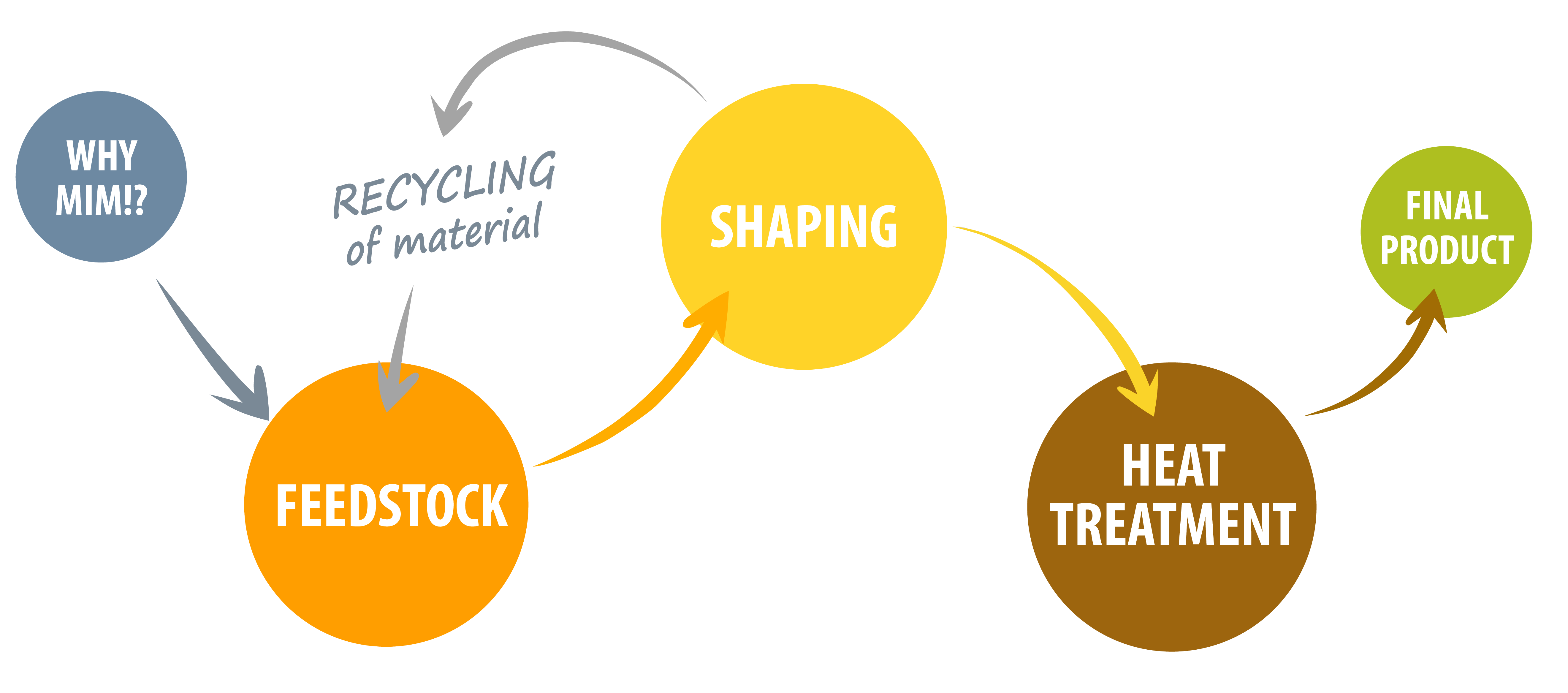
The process is based on a fine metal powder that is combined with a polymeric binder to form a mouldable feedstock. After injection moulding, the binder is removed and the component is compacted by sintering. This produces parts with contours close to the final shape and mechanical properties that closely resemble those of forged materials.
1. Produce feedstock
To produce the feedstock, suitable metal powders are selected on the basis of their particle size, morphology and chemical composition in order to achieve high sintered densities and the desired mechanical properties.
These powders are homogeneously mixed with a thermoplastic polymer binder system. The binder holds the powder together during the shaping process and ensures the necessary viscosity during injection moulding.
The mixing process is crucial for ensuring:
• uniform binder distribution,
• consistent material properties,
• the required flowability.
2. Injection moulding components
The feedstock is heated in the injection unit and brought to a molten state. It is then injected into a precision-machined mould that replicates the negative contour of the component.
Once cooled, the so-called green part is ejected. This still contains the entire binder system and must be debound before final compaction.
3. Debinding and sintering
Debinding
Debinding is usually carried out in two stages:
• Chemical/catalytic: Removal of the main binder using suitable agents (catalysts, solvents, water).
• Thermal: Decomposition of the remaining backbone binder in a furnace.
The resulting brown part already has its final geometry, but is extremely fragile.
Sintering
During sintering, the components are heat-treated to just below their melting point. Through atomic diffusion, they compact and achieve almost the theoretical material densities.
Typical characteristics:
• Shrinkage: 15–22 %
• Increase in strength and hardness
• Minimisation of residual porosity
• Required process atmospheres: inert or reducing
Careful temperature and atmosphere control prevents warping, oxidation or undesirable microstructural changes.
4. Further processing
MIM components can be further processed in the same way as conventionally manufactured metal components. Typical subsequent processes include:
- Surface finishing: sandblasting, vibratory finishing, polishing, lapping
- Coating technologies: thin-film processes, electroplating, painting
- Joining techniques: laser welding, brazing, assembly
- Heat treatment: hardening, hot isostatic pressing (HIP)
- Machining: turning, milling, drilling, grinding, reaming, honing
- Forming techniques: bending, calibrating
Materials & Mechanical Properties
MIM materials exhibit excellent mechanical properties due to their fine powder structure and near-complete densification. Residual porosity is minimal and consists of round, isolated pores that are evenly distributed throughout the microstructure.
- Tests are carried out in accordance with ISO 2740, for example
- Many materials are heat-treatable
- Mechanical properties are comparable to those of forged materials
- Available material groups:
o Stainless steels (e.g. 316L, 17-4PH)
o Tool steels
o Titanium and titanium alloys (e.g. TiAl6Nb7, Ti6Al4V)
o Magnetic materials
o Precious metals
o Special alloys (e.g. shape memory alloys)
Advantages & limitations of the MIM process
Advantages
- Degrees of freedom similar to those in plastic injection moulding
- Manufacturing with near-net-shape accuracy
- Ideally suited to complex geometries
- Cost-effective for medium and large production runs
- High reproducibility and process automation
- Mechanical properties comparable to forged materials
- Integrated functional features:
o Undercuts
o Internal threads, external threads
o Cross-drilled holes
o Gear teeth
o Markings
o Surface textures
Limitations
- Usually not cost-effective for very low production volumes
- Wall thicknesses > 25 mm are critical
- Unfavourable flow paths can lead to porosity or bonding defects
- Mechanical properties depend on the material and process
Examples of applications (selection)
MIM technology is used across a wide range of industries – from medical technology and the automotive industry to electronics, optics and consumer goods.
Examples:
- Artificial heart valve, titanium alloy TiAl6Nb7
- Canulated double-threaded screw, medical technology
- HV nut core, automotive
- Watch case, 316L
- ‘Tag Heuer’ spring hinge, eyewear industry
- Ballpoint pen clip, FeNi7
- Magnetic pot, electrical engineering
- Components made from NiTi shape memory alloys
- MIM tensile test bar in accordance with DIN ISO 2740
These examples illustrate the range of possibilities in terms of geometry, materials and functional integration.
MIM – Why this process?
The trend towards miniaturised, high-precision and functionally dense components requires manufacturing technologies that are both technically and economically compelling.
MIM offers decisive advantages here:
- Maximum design freedom
- Integration of complex functions within the mould
- Reproducible series production
- High-quality material properties
- Cost advantages as complexity increases
It is therefore a key technology for modern product developments that require complex, high-performance and, at the same time, cost-efficient components.